Table of Contents
Study Guide 7: I/O
I/O devices can be categorized based on how they access data, also known as access patterns. Character devices (e.g. keyboard, printer) access data as a character stream, meaning data is not addressable. On the other hand, block devices (e.g. disk) access data in fixed-sized blocks. Data is addressable (i.e. able to seek). Network devices (e.g. ethernet, wireless, Bluetooth) have a separate interface for networking purposes (e.g. socket interfaces like select).
I/O devices can also be categorized based on the access timing. Synchronous or blocking interfaces wait until an I/O request is fulfilled. On the other hand, non-blocking interfaces return quickly from a request without waiting. Asynchronous interfaces allow other processing to continue while waiting for the request to complete. For instance, when requesting data, the request will return immediately with a pointer to a buffer. This buffer will be filled asynchronously. When the request is completed, the process will be notified with a signal It’s important to note that while synchronous and blocking are synonymous, non-blocking and asynchronous are two distinct types of non-synchronous I/O.
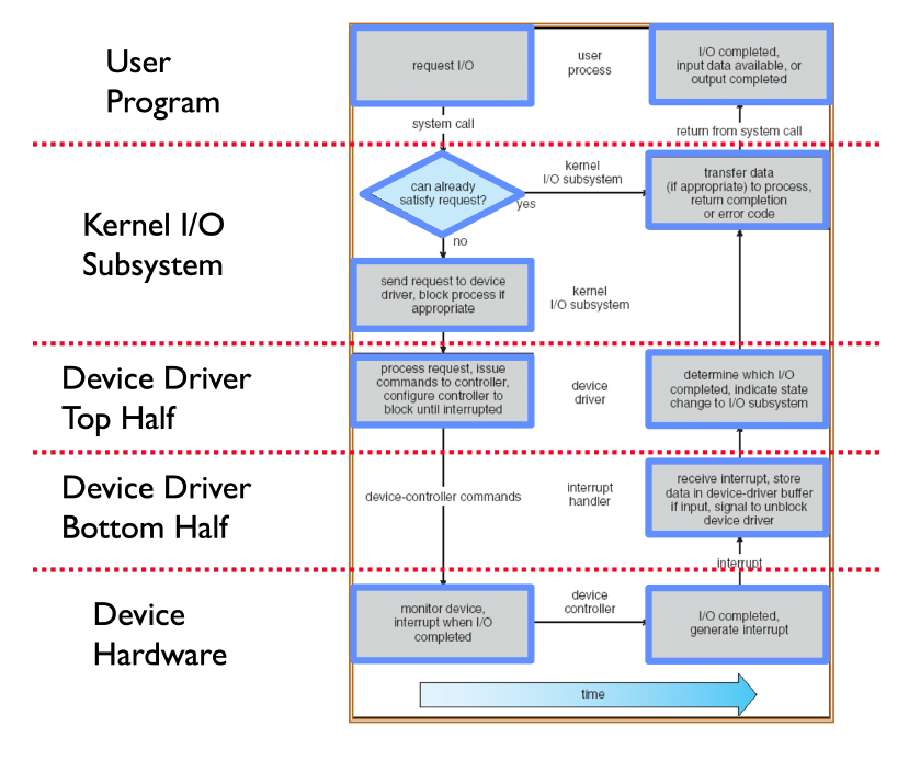
To provide an easy to use abstraction for I/O, device drivers connect the high-level abstractions implemented by the OS and hardware specific details for I/O devices. They support a standard interface allowing the kernel to use hardware without knowing the specific implementation. Device drivers are split into two halves. The top half is used by the kernel to start I/O operations, while the bottom half services interrupts produced by the device. It’s important to note that in Linux, the terms are flipped.
Device Access
Processors talk to I/O devices through device controllers, which contain a set of registers that can be read from and written to. When using programmed I/O (PIO), the processor is involved in every byte transfer. This can be done using port-mapped I/O (PMIO) which uses special memory instructions (e.g. in/out in x86). The memory address space is distinct from the physical memory address space. This is useful on older/smaller devices with limited physical address space, but it complicates CPU logic with special instructions. Alternatively, memory-mapped I/O (MMIO) maps control registers and displays memory into the physical address space. It uses standard memory instructions (load, store). As a result, it will use up a portion of the physical memory address space. However, this simplifies CPU logic by putting the responsibility on the device controller.
On the other hand, direct memory access (DMA) allows the I/O device to directly write to main memory without CPU intervention. It uses memory addresses within the physical memory region contrary to MMIO which just shares the same physical address space.
When an I/O operation is completed, the OS needs to be notified regarding its success. Polling puts this responsibility on the OS, requiring the OS to repeatedly check a memory-mapped status register. This provides a low-cost method since it would effectively be a memory access. However, it’s not a very efficient use of CPU cycles, especially for infrequent or unpredictable I/O. On the other hand, the I/O device could generate an interrupt. This is much more expensive due to context switching overhead, but it’s easier to handle infrequent or unpredictable requests.
Storage Devices
Magnetic Disks
Magnetic disks use magnetization to read and write data. Each magnetic disk is comprised of multiple platters, single thin round plates that store information. Each platter spins on a spindle, where each platter has two surfaces. Data is read and written with the head. Each head attaches to an arm, and each arm attaches to the arm assembly. Data is stored in fixed size units called sectors, which are the minimum units of transfer. A circle of sectors makes up a track. Due to the geometry of a disk, the track length varies from the inside to the outside of the disk.
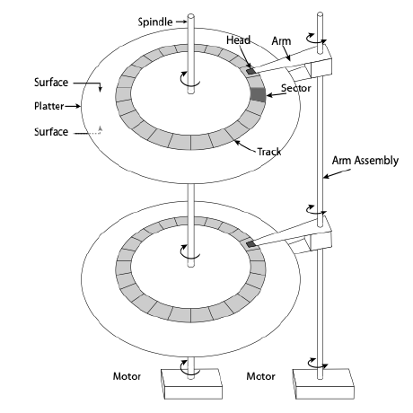
As seen in the picture above, magnetic disks have lots of moving parts, which can lead to many physical issues. Compared to flash memory in the next section, the read/write times are a lot slower. However, they are much cheaper compared to flash memory, offering a better data size to price ratio.
Flash Memory
Flash memory uses electrical circuits (e.g. NOR, NAND) for persistent storage. While NOR flash allows individual words to be read/written, we will focus on NAND flash which reads/writes in fixed size units called pages (typically 2 KB to 4 KB). Flash memory involves much fewer moving parts compared to magnetic disks, leading to more durability. Its read and write speeds are also much faster. However, writing to a cell requires erasing it first (i.e. can’t override the value). Erasing can only be done in large units called erasure blocks (typically 128 KB to 512 KB). Furthermore, each page has a finite lifetime, meaning it can only be erased and rewritten a fixed number of times (e.g. 10K).
To address the concern of erasure blocks, flash memory typically uses a flash translation layer (FTL) maps logical flash pages to different physical pages on the device. This allows the device to relocate data without the OS knowing or having to worry about it. As a result, writing over an existing page would involve writing to a new location, updating the mapping in the FTL, and then erasing the old page in the background. To ensure all physical pages are used roughly equally, the FTL uses wear leveling.
Performance
It’s important to minimize how long it takes to access data from a storage device. The time required to retrieve data typically involves queuing time, controller time, and access time. Queuing time refers to how long a data request spends in the OS queue before actually getting fulfilled. Controller time refers to how long the device controller spends processing the request. Access time refers to how long it takes to access data from the device. When discussing performance between different devices, the access time is what will generally be focused on.
For magnetic disks, the access time involves the seek time, rotation time, and transfer time. Seeking moves the arm over to the desired track. Then, we need to wait for the target sector to rotate under the head. Finally, the disk must transfer data to/from the buffer for read/write. When maximizing disk performance, the key is to minimize seek and rotation times since transfer times are fixed for a given disk.
To improve disk performance, disks employ several intelligence techniques. Track skewing staggers logical sectors of the same number on each track by the time it takes to move across one track. Sector sparing remaps bad sectors to spare sectors on the same surface. Disk manufacturers typically include spare sectors distributed across each surface for this. To preserve sequential behavior, disks may use slip sparing which remaps all sectors when there is a bad sector. Disks often include a few MB of buffer memory which is used by the disk controller to buffer data for reads and writes. As a result, track buffering can improve performance by storing sectors that have been read by the disk head but not requested by the OS, taking advantage of physical spatial locality.
Concept Check
If a particular I/O device implements a blocking interface, do you need multiple threads to have concurrent operations which use that device?
Solution
Yes. Only with non-blocking IO can you have concurrency without multiple threads.
For I/O devices which receive new data very frequently, is it more efficient to interrupt the CPU than to have the CPU poll the device?
Solution
No. It is more efficient to poll, since the CPU will get overwhelmed with interrupts.
When using SSDs, which between reading or writing data is complex and slow?
Solution
SSDs have complex and slower writes because their memory can’t easily be mutated.
Why might you choose to use DMA instead of MMIO? Give a specific example where one is more appropriate than the other.
Solution
DMA is more appropriate when you need to transfer large amounts of data to/from main memory without occupying the CPU, especially when the operation could potentially take a long time to finish (accessing a disk sector, for example). The DMA controller will send an interrupt to the CPU when the DMA operation completes, so the CPU does not need to waste cycles polling the device. While memory mapped I/O can be used to transfer device data into main memory, it must involve the CPU. MMIO is useful for accessing devices directly from the CPU (writing to the frame buffer or programming the interrupt vector, for example).
Usually, the OS deals with bad or corrupted sectors. However, some disk controllers magically hide failing sectors and re-map to back-up locations on disk when a sector fails. (a) If you had to choose where to lay out these “back-up” sectors on disk - where would you put them? Why?
Solution
You should spread them out evenly, so when you replace an arbitrary sector your find one that is close by.
(b) How do you think that the disk controller can check whether a sector has gone bad?
Solution
Using a checksum, this can be efficiently checked in hardware during disk access.
(c) Can you think of any drawbacks of hiding errors like this from the OS?
Solution
Excessive sector failures are warning signs that a disk is beginning to fail.
When writing data to disk, how can the buffer memory be used to increase the perceived write speed from the OS viewpoint?
Solution
Data written to disk can actually be stored in the buffer memory. Once this buffer memory is written to, the disk can acknowledge to the OS that the write has completed before it is actually stored on persistent storage. The buffer would get flushed to the platter at some later time. This technique is known as write acceleration.
Hard Drive Performance
Assume we have a hard drive with the following specifications.
- An average seek time of 8 ms
- A rotational speed of 7200 revolutions per minute (RPM)
- A controller that can transfer data at a maximum rate of 50 MiB/s
We will ignore the effects of queuing delay for this problem.
What is the expected throughput of the hard drive when reading 4 KiB sectors from a random location on disk?
Solution
The time to read the sector can be broken down into three parts: seek time, rotation time, and transfer time.
We are already given the expected seek time: 8 ms.
On average, the hard disk must complete 1/2 revolution before the sector we are interested in reading moves under the read/write head. Given that the disk makes 7200 revolutions per minute, the expected rotation time is:
\[\frac{1}{2} \times \frac{1}{7200rpm} \approx 4.17 ms\]If the controller can transfer 50 MiB per second, it will take:
\[4 KiB \times \frac{1}{50MiB} \approx 0.078125 ms\]to transfer 4 KiB of data.
In total, it takes \(8 ms + 4.17 ms + 0.078125 ms \approx 12.248 ms\) to read the 4 KiB sector, yielding a throughput of:
\[\frac{4 KiB}{12.248 ms} \approx 326.6 KiB/s\]
What is the expected throughput of the hard drive when reading 4 KiB sectors from the same track on disk (i.e. the read/write head is already positioned over the correct track when the operation starts)?
Solution
Now, we can ignore seek time and only need to account for rotation time and transfer time. Therefore, it takes a total of:
\[4.17 ms + 0.078125 ms \approx 4.24 ms\]to read the 4 KiB sector, yielding a throughput of:
\[\frac{4 KiB}{4.24 ms} \approx 943.4 KiB/s\]
What is the expected throughput of the hard drive when reading the very next 4 KiB sector (i.e. the read/write head is immediately over the proper track and sector at the start of the operation)?
Solution
Now, we can ignore both seek and rotation times. The throughput of the hard disk in this case is limited only by the controller, meaning we can take full advantage of its 50 MiB/s transfer rate. Note that this is roughly a \(156\times\) improvement over the random read scenario!